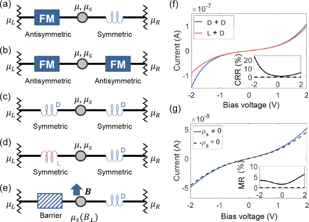
Figure 4.
Generic 2T spin-valve device geometries with the symmetry of the charge–spin transport matrix labeled for each component. (a) The aforementioned FM–chiral geometry where MR signals are strictly forbidden in the linear response regime. (b) An FM–FM geometry, as in a conventional spin valve, where MR signals are allowed in the linear response regime. (c, d) A chiral–chiral geometry for using the same (c) and opposite (d) chiralities, as marked by color and labeled with d or l (here we assume the d-chiral component favors the transmission of electrons with spin parallel to momentum, and the l-chiral component favors the antiparallel ones). The spin-valve effect can be achieved, even in the linear response regime, by reversing the chirality of one component. (e) Geometry for directly probing the spin accumulation generated by a single chiral component, which is connected to a nonmagnetic barrier via a node. A perpendicular magnetic field B suppresses spin accumulation in the node via Hanle spin precession. (f) Example I–V curves for a chiral−chiral spin valve, with the two curves representing the geometries in panel (c) and (d), respectively. The corresponding chirality-reversal resistance (CRR) ratio, as defined by CRR = (Idd – Ild)/(Idd + Ild) (the two subscripts refer to the chiralities of the two chiral components), is plotted in the inset. (g) Example I–V for the geometry in panel (e), calculated for cases with μs either fully or not-at-all suppressed by Hanle precession. The corresponding MR is shown in inset, which is defined as the difference of the two curves divided by their sum.

