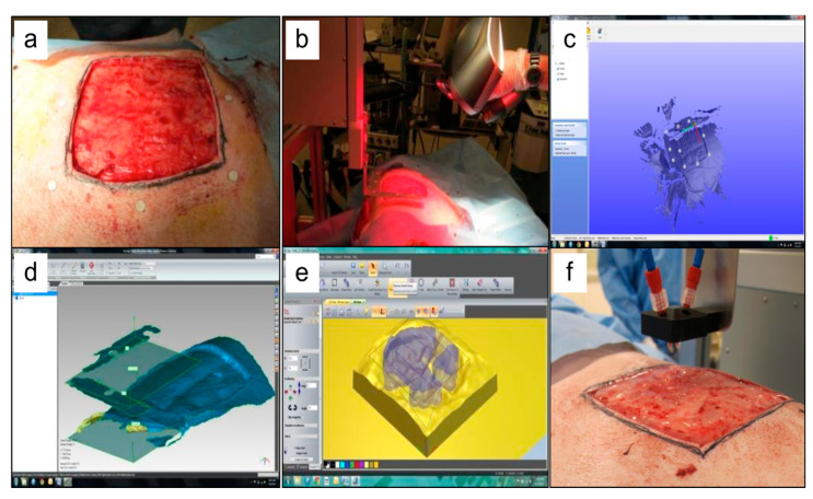
Figure 2.
Example of in situ skin bioprinting process, where, (a) Markers are placed around the wound area as reference points; (b) Wound area scanned with a hand-held ZScanner™ (Z700 scanner); (c) Geometric information obtained via scanning is then inputted in the form of an STL file to orient the scanned images to the standard coordinate system; (d) The scanned data with its coordinate system is used to generate the fill volume, and the path points for nozzle head to travel to print the fill volume; (e,f). Output code is then provided to the custom bioprinter control interface for generation of nozzle path needed to print fill volume. Figure and caption reused from Albanna et al. [31]. Used under the Creative Commons License (http://creativecommons.org/licenses/by/4.0/).

