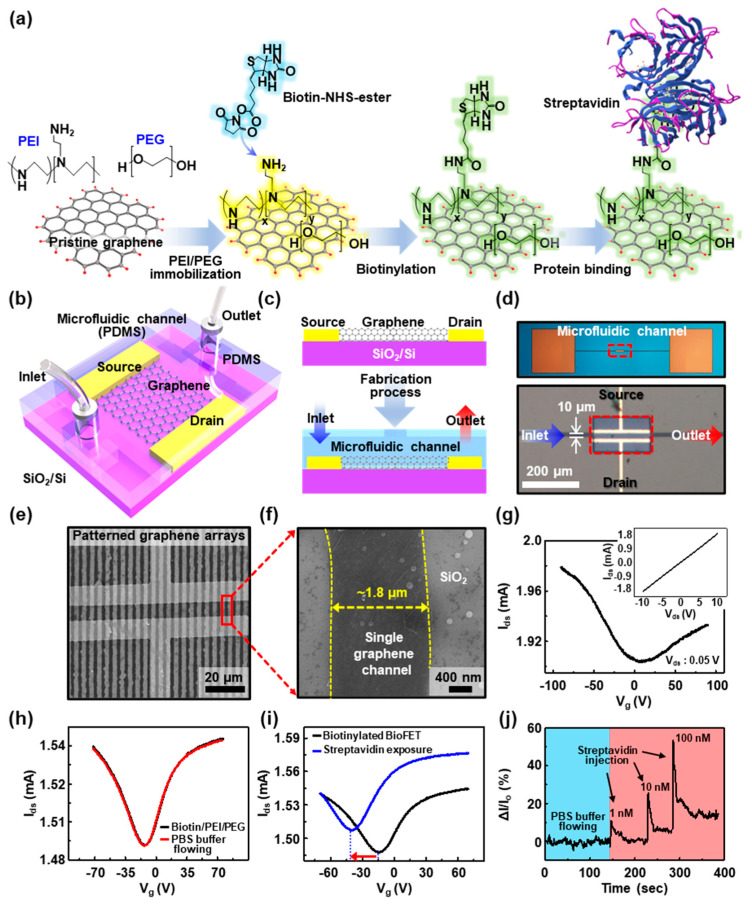
Figure 6.
(a) Schematic diagram of the chemical modification steps on the graphene active channels to generate the BioGFET. (b) Structure of the BioGFET, integrated with a microfluidic channel. (c) A cross-sectional view of a microfluidic channel system built with BioGFET. (d) Optical micrographs of BioGFETs with a microfluidic channel. (e) SEM image of the chemically modified graphene multichannel, built with electric pads. (f) Zoom-in image of a single channel of the patterned graphene. (g) Gate voltage dependence of source-drain current before the surface modification with biotin/poly(ethylene imine) (PEI)/poly(ethylene glycol) (PEG); inset: current density–voltage (I–V) characteristics for a representative device. (h) Transfer characteristics according to the flowing of phosphate-buffered saline (PBS) buffer solution after biotin/PEI/PEG polymer coating on the graphene channels. (i) Transfer characteristics before and after streptavidin exposure on the active channels in BioGFET. (j) The signal was measured by monitoring the current as a function of time for different concentrations of streptavidin.

