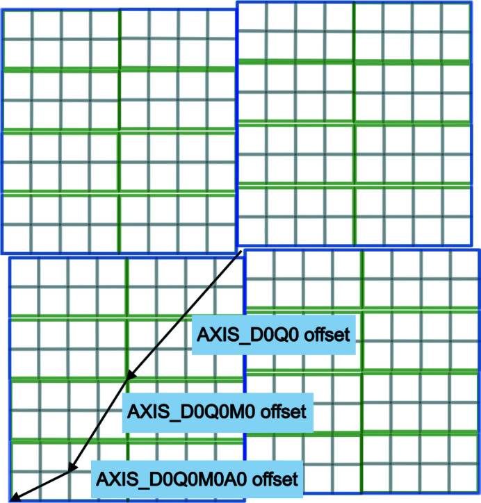
Figure 1.
Schematic of the JF16M detector viewed from the source side, showing the hierarchical arrangement of panels. The quadrants are outlined in blue, the modules in green and the ASICs in gray. The offset components of the NeXus transformations are shown as arrows for the quadrant zero, sensor zero and ASIC zero. Note that the arrows point in the directions of the offsets, which are in the X–Y plane, not in the directions of the axes themselves, which are in the Z direction.

