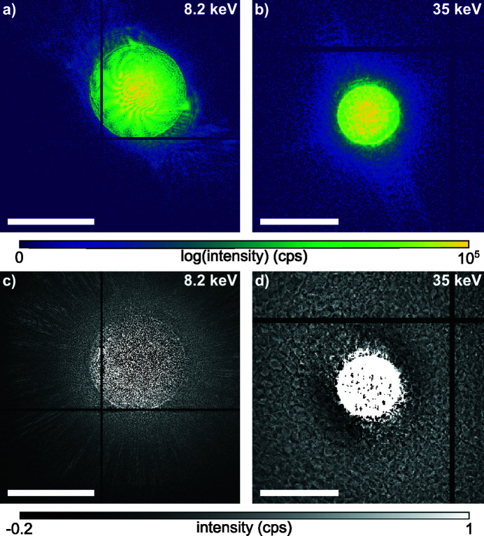
Figure 3.
Example of diffraction patterns and average background signal, which is calculated from the difference between measured data and modeled diffraction patterns from ptychography. (a) Cropped diffraction pattern recorded with a Merlin detector at 8.2 keV. The beam is off-center as the detector ends in the upper right corner. (b) Cropped diffraction pattern at 35.0 keV recorded with the Lambda 2M GaAs detector. (c) Average background at 8.2 keV with the Merlin Si sensor. (d) Average background at 35 keV with the Lambda GaAs sensor. The scale bar in all images represents a scattering vector of 0.1 nm−1.

