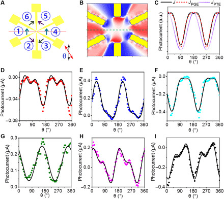
Fig. 4. Polarization-resolved photocurrent in a circularly arranged contact device.

(A) Schematic diagram of the experimental setup for polarization-resolved photocurrent measurement. The photocurrent was collected between nearest electrode pairs around the sample in the sequence of anticlockwise. θ is the angle of incident light polarization. (B) Simulated distribution of PGE photocurrent at θ = 45° (see fig. S5 for additional angular configurations). (C) Dependence of the photocurrent on polarization angle θ. JPGE derives from PGE, and JPTE is related to PTE. J = Asin(4θ + a) + Bcos(2θ + b) + C. (D to I) Dependence of the photocurrent on different electrode pairs (① to ⑥) on polarization angle θ.
