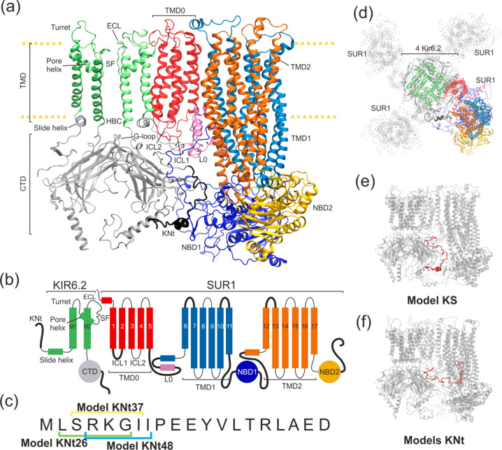
Figure 1.
Structural details of the KATP models used in this work. (a) Ribbon representation of two Kir6.2 in one SUR1 system. The disordered region of KN tail is placed outside the SUR1 cavity (model KS) and is shown as a thick black ribbon. (b) Domain architecture of the system. Black bold lines denote regions where no clear density was observed in the cryo-EM outward open structure. (c) The sequence of the KN tail region, with three N-terminal peptides used in the tail model building indicated. (d) Top view of the KATP octamer (outward open). The shaded part represents domains which were not included in our modeling. The colored part is included in model K (four Kir6.2 proteins) and model KS (four Kir6.2 and one SUR1 protein). (e) Possible positions of the disordered KN tail region (red) in model KS and (f) N tail-constrained variants of model KS named models KNt. A color representation of domains remains the same throughout the paper.

