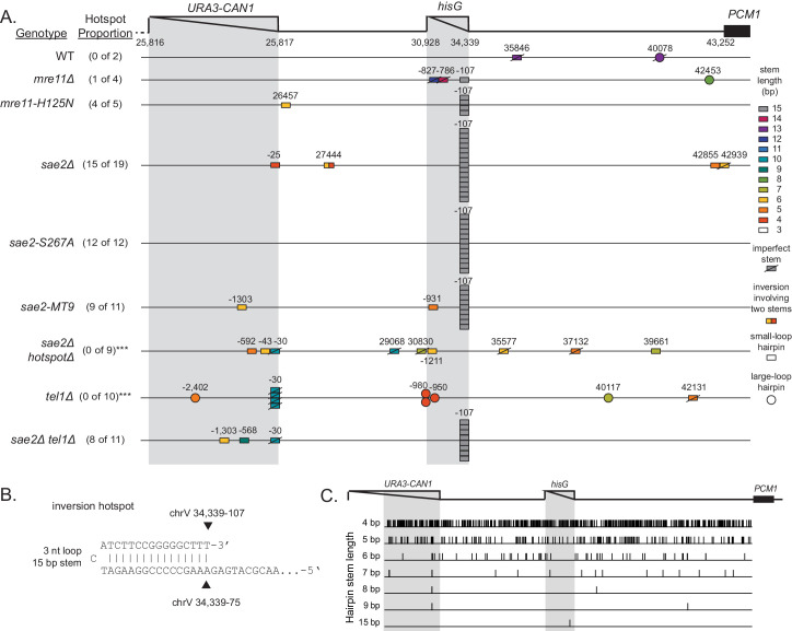
Figure 3. Distribution of inversion junctions in mre11 and sae2 mutants.
(A) Map of the position of the inversion junctions (boxes) reveals that an inversion hotspot in the hisG insertion mediates a large proportion of the foldback inversions in strains with mre11 and sae2 defects. Each observed inversion is represented by a separate box (short loop hairpin) or separate circle (large loop hairpin) at the inversion junction position; for example, the 15 grey boxes corresponding to the inversion hotspot (labeled ‘−107’) on the sae2Δ line correspond to 15 independent GCR-containing strains isolated from the sae2Δ single mutant that have an inversion at the hotspot. The only mutants whose usage of the inversion hotspot relative to other inversion sites was altered relative to the sae2Δ single mutant control were the sae2Δ hotspotΔ and tel1Δ mutants (p=0.0002 and p=5×10⁻⁵; Fisher’s exact test). ‘Imperfect stem’ indicates stems predicted to contain one or more mispairs or unpaired bases by MFOLD (Zuker, 2003). (B) The predicted ssDNA hairpin for the inversion hotspot is predicted by MFOLD to form a 15 bp stem with a three nt loop. (C) The inversion hotspot contains the longest stem structure for any of the theoretically predicted sites with a propensity to form ssDNA hairpins in the uGCR chrV L breakpoint region. Predicted hairpin sites were restricted to a loop size of <50 nt and were not allowed to have mismatches in the stems.

