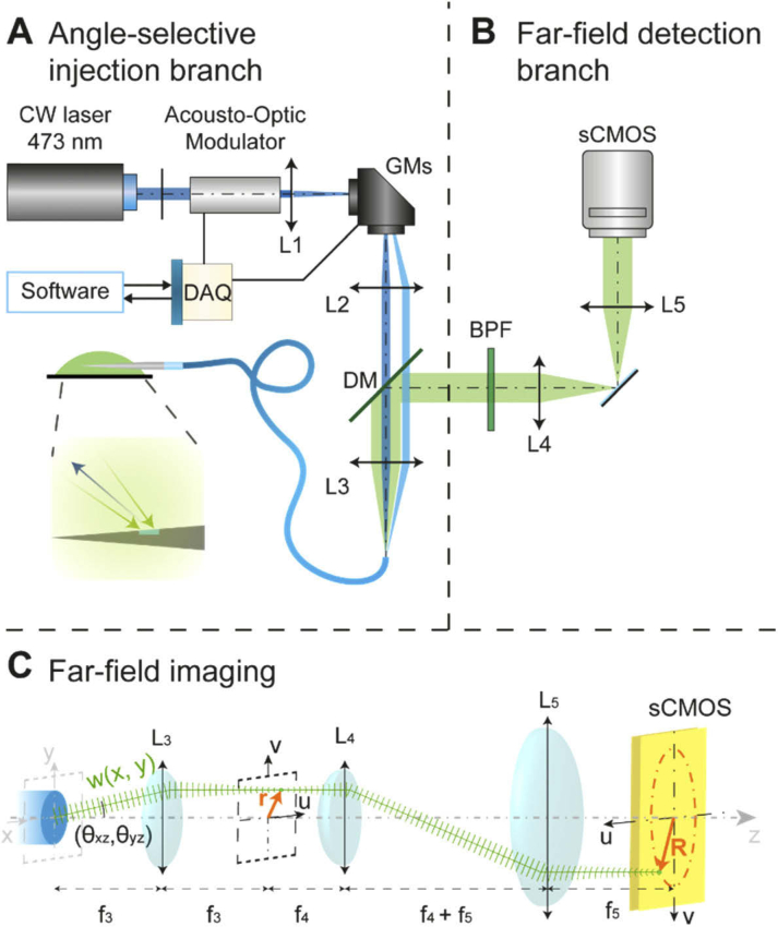
Fig. 4.
(a) Sketch of the light emitted by the fiber and the correlation between the emission angle and the coordinates on the focal plane. (b) Scheme of the optical setup employed for angle selective light coupling inside the fiber and (B) far-field imaging of the collected signal. (c) Sketch of the light emitted by the fiber and the correlation between the emission angle and the coordinates on the detection plane (Band Pass Filter BPF is omitted).

