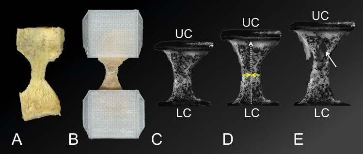
Figure 1.
The images display the preparation steps of samples for tensile testing and the subsequent uniaxial load application at different testing stages. (A) A lateral calcaneal periosteum sample is depicted after it has been cut into a “dog bone” shape (view from inside). (B) The sample from A was mounted into 3D-printed squeezing clamps (view on the sample from outside). (C) Speckled and mounted sample in the material testing machine, upper (UC) and lower (LC) clamp. (D) A load is applied to the sample, indicated by the UC crosshead displacing cranially. The sample elongates (represented by the dotted arrow) and narrows in the ‘shaft’ region of the dog bone, indicated by the yellow arrows. (E) Continuous load application causes tearing of the sample (indicated by the white arrow).

