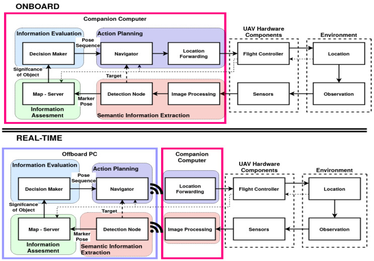
Figure 1.
Modules developed in [35], onboard (top) and a real-time (bottom) configuration, with the system load distributed across a PC (purple) and an onboard computer (magenta). The thin dashed line indicates a serial connection and the wireless symbol a network connection. Differences in software set-up are called configurations in this work.

