
Fig. 2. Creating magnetic skyrmions in FGT by the magnetic interlayer coupling between FGT and [Co/Pd]10 multilayers.
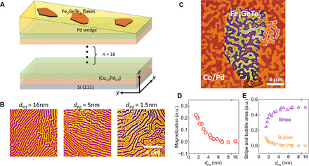
(A) Schematic drawing of the sample structure, where the wedged Pd spacer layer tunes the coupling strength between FGT and perpendicularly magnetized [Co/Pd]10 multilayers. (B) PEEM images of the FGT magnetic domains at three different thicknesses of the Pd spacer layer. The bright and dark contrasts correspond to an out-of-plane magnetization in the +z and –z directions, respectively. The [Co/Pd]10 underlayer was magnetized in the +z direction. Dark stripes are gradually broken into bubbles (skyrmions) as the coupling strength increases by decreasing the Pd thickness. The thicknesses of FGT flakes are 130, 150, and 130 nm, respectively. (C) Magnetic domain images of the FGT obtained at Fe L3 edge (the center flake) and the [Co/Pd]10 obtained at Co L3 edge (surrounding area) at dPd = 0.9 nm after demagnetizing the [Co/Pd]10 into multidomains. The magnetization direction inside the bubbles is always antiparallel to the underlayer [Co/Pd]10 magnetization. (D) FGT normalized magnetization calculated from the areal difference between the bright and the dark domains of the PEEM images and (E) from areal fractions of stripes and bubbles (antiparallel to [Co/Pd]10 magnetization) as a function of Pd spacer layer thickness.