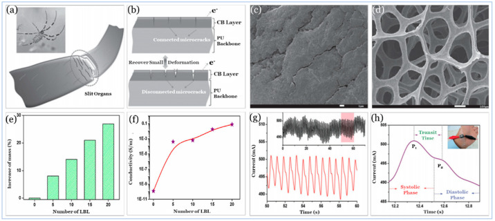
Figure 11.
CB@PU Sponge. Reproduced with permission [240] Copyright 2016, Wiley. (a) Sketch of the crack-shaped slit organs near the leg joints of the spider. (b) SEM images of the microcrack junctions on a CB@PU sponge after compressing pre-treatment. (c) SEM images of an uncompressed CB@PU Sponge. (d) Comparison of mechanical properties of CB@PU Sponges with different Layer By Layer (LBL) deposition cycles of CB, a relative increase of CB mass on PU Sponges, (e) and an increase in conductivity of CB@PU Sponges. (f) with different LBL deposition cycles of CB. (g) Original signal of current curves for wrist pulse monitoring. (h) Zoomed waveform extracted from the original signal, showing some critical features that are essential for health monitoring.

