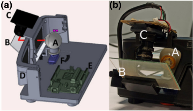
Figure 4.

Eye tracking demonstrator (a) schematic of the overall system depicting the artificial eye (A) on which the cyclops lens is mounted, the servo-motor (F) and associated micro-controller (E) to control the eye direction, the eyewear (D) with the primary antenna, the beam splitter (B) reflecting the VCSEL beam (represented by a solid red line) towards the IR camera (C) (mounted on top of the eyewear). (b) A photo of the prototype.
