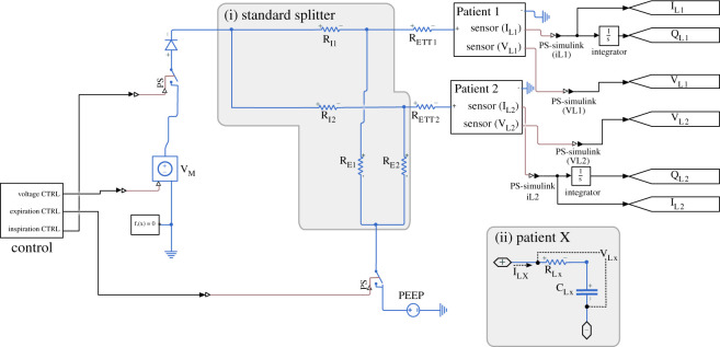
Figure 1.
Circuit diagram for the standard splitter. The control module contains a pulse-wave generator with a period appropriate to the respiration rate. It delivers three square signals to control the inspiration, expiration and voltage to the circuit. The RETT resistors correspond to the endotracheal tubing. REx and RIx correspond to the inflow and outflow tubing resistance. The patient module consists of a resistor (RLx) to model upper airway resistance, and a capacitor CLx, to model the compliance of the lungs and chest wall. Grey boxes outline the splitter (i) and patient submodule (ii). The text ‘sensor’ on the patient blocks indicate that the respective signals are connected to appropriate Simscape sensor blocks, namely current and voltage sensors, to allow for these signals to be logged during simulation.

