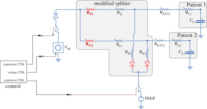
Figure 2.
Circuit diagram for the modified splitter. Compared to figure 1, variable resistors RV1 and RV2 have been added to control the pressure/flow/volume to each patient, and diodes have been added to stop the expiration arms acting as a short circuit between inspiration arms during inspiration. Changes with respect to the standard circuit are highlighted in red.

