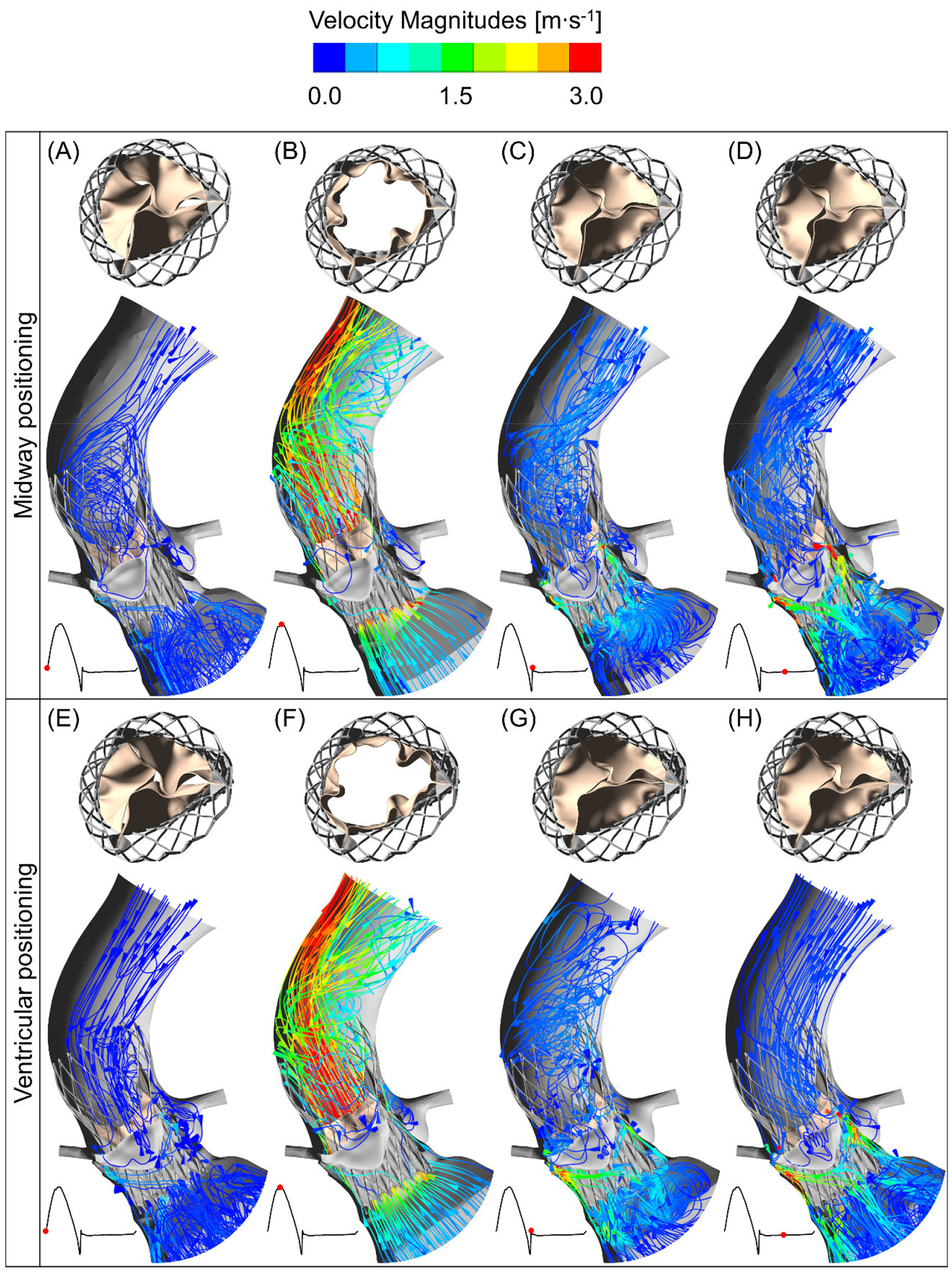
Figure 4:

The midway and ventricular positioning flow velocity streamlines at four different instances during cardiac cycle. The top row (A–D) shows the deployed TAVR valve hemodynamics in the midway positioning during a cardiac cycle and top view of the prosthetic leaflet kinematics at their corresponding instances. The TAVR valve ventricular positioning hemodynamics and the top view of the valve opening are shown in the bottom row (E–H).
