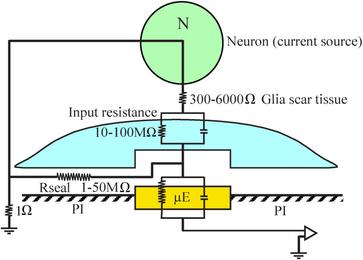
FIGURE 15.
A minimal analog electrical circuit depicting the relationships between a current source - neuron (N, green) and an implanted microelectrode (μE yellow) to account for the abrupt attenuation of the FP amplitude by microglia (blue) that adheres to the microelectrode surface and the polyimide substrate around it (PI, gray). The configuration shows the current source (neuron), a resistor representing the scar tissue in series with the input resistance of a glia cell adhering to the electrode and the electrode impedance. The resistance formed by the extracellular space between the adhering cell (blue) and the microelectrode (yellow) is represented by the seal resistance (Rseal). The brain tissue resistance between the current source (neuron) and the ground is depicted on the left hand side. The given resistance values are orders of magnitude estimates from the literature. For additional information, see text.

