
Figure 3.
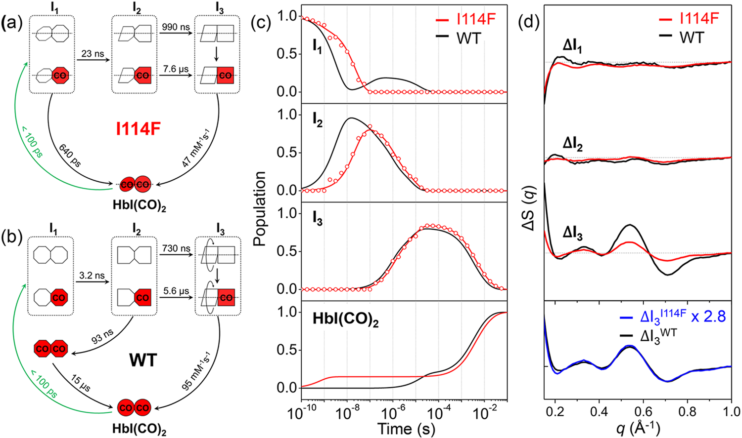
(a, b) Kinetic models for I114F and WT. The red (with “CO”) and white symbols represent ligated and photolyzed subunits, respectively. To indicate the three structurally distinguishable intermediates with different tertiary structures, the subunit of each intermediate is presented with a different shape. For all three intermediates and HbI(CO)2 of I114F, two subunits are described as rotating with respect to the other, reflecting the quaternary structural difference with respect to the R state of WT, that is, the liganded state of WT. For WT, only I3 is represented in such a way, indicating that the quaternary transition involving subunit rotation occurs only in I3. In the kinetic model for WT, two connected red octagons represent a ligated form of I1, which is formed by the geminate recombination of CO with I2 and structurally indistinguishable from the photolyzed forms (two connected white octagons and the white-red mixed ones) of I1. (c) Population changes of the three intermediates and initial HbI(CO)2 as a function of time for I114F (red) and WT (black). The lines correspond to the populations obtained from the kinetics analysis. The open circles correspond to the optimized populations obtained by fitting the experimental curve at each time point with a linear combination of SADS curves for the three intermediates. (d) SADS curves of the three intermediates for I114F (red) and WT (black). The scaled curve of I3I114F (blue) has a shape nearly identical to that of I3WT, but with a smaller magnitude by 2.8 times.