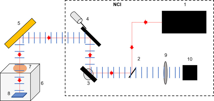
Fig 3. Schematic representation of the imaging set up.
(1) The Intracavity Optical Parametric Oscillator (ICOPO) provides the IR illumination for measurements. The (2) gold coated steering mirror, (3) y-axis galvanometer mirror and (4) x-axis galvanometer mirror are also housed in the NCI system. (5) External gold coated steering mirror, (6) custom built transport chamber, (7) Calcium Fluoride (CaF2) viewing window all allow for the imaging of the (8) sample, within a sterile environment. The reflected light then retraces its path before passing through a (9) CaF2 focusing lens and onto the (10) MCT detector.

