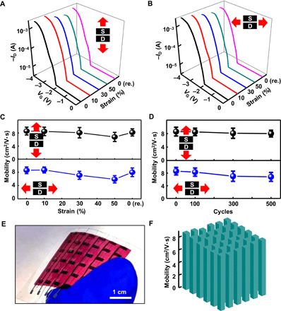
Fig. 3. Rubbery transistor under mechanical strain.

(A and B) Representative transfer curves of the intrinsically stretchable transistors under mechanical strains of 0, 10, 30, 50, and 0% (released) along (A) and perpendicular (B) to the channel length direction. (C) Changes of the mobility during stretching to 50% strain along and perpendicular to the channel length direction. (D) Changes of the mobility after stretch-release cycles at 30% strain along and perpendicular to the channel length direction. (E) Photograph of the transistor array. (F) Mobility distribution in the transistor array. Photo credit: Ying-Shi Guan, University of Houston.
