
Figure 2.
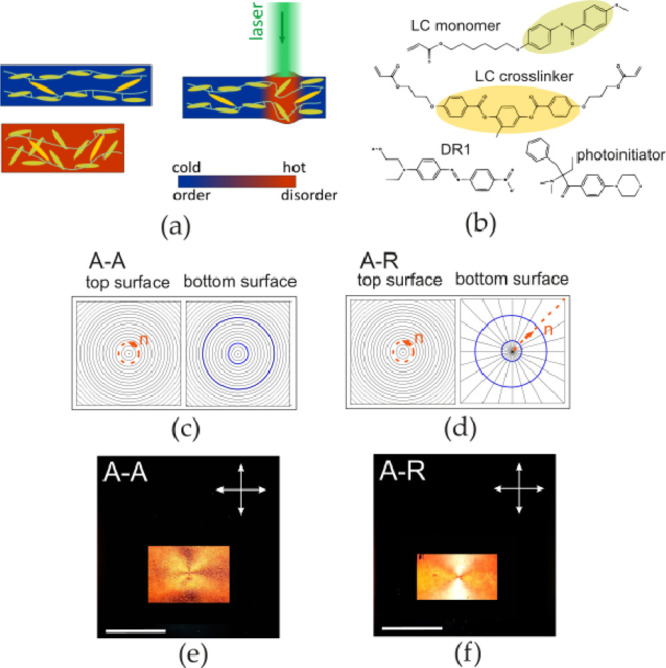
(a) Cross-linked polymer chains (yellow) arranged in one direction in an LC polymer network stripe deform locally because of increased temperature. With efficient light-absorbing dye, the heating can be induced by light absorption from a laser beam. (b) LC monomer, cross-linker, dye (Disperse Red 1) and photoinitiator used in the LCN. The coloring is consistent with panel (a). (c,d) Orientation of the molecular director n at the top and bottom surfaces of the cells used for preparing the LCN films: azimuthal (A) and radial (R). Two types of LCN films were prepared: A–A and A–R. Blue rings present how the micromotor rotor was cut from the film. (e,f) A–A and A–R cells filled with the LCN mixture, observed with a polarizing optical microscope (the arrows indicate the polarizer and analyzer orientation). The white scale bars in the photos are 10 mm long.