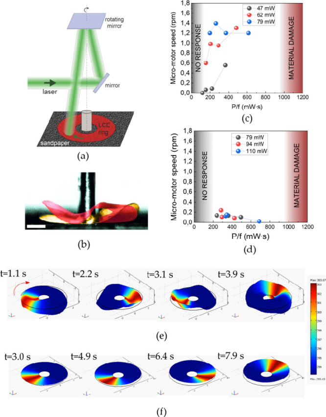
Figure 3.

(a) Schematic of the experimental setup. The laser beam is reflected from a rotating mirror and sweeps around the LCN rotor ring. (b) Static LCN ring deformation due to the photomechanical response: yellow and red (computer-added colors) areas are images of the ring without and with the laser on, respectively. The white scale bar in the photo is 1 mm long. (c) LCN micromotor speed varies with the increasing P/f ratio, where P is the laser power and f is the mirror rotation frequency. Rotor with A–R orientation. (d) Same as (c) for the rotor with A–A orientation. (e) Snapshots of the numerical simulation of the traveling LCN ring deformations for the A–R orientation. (f) Same as (e) for the A–A orientation.
