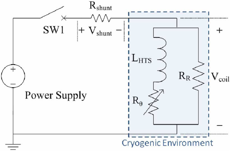
Fig. 2.
Electrical circuit diagram with a DC power supply, a test coil in cryogenic environment (shaded section), a shunt resistor, and a switch—all connected in series. Three components in the equivalent circuit model of the NI test coil: LHTS (self inductance of HTS winding); Rθ (azimuthal resistance including index loss and matrix resistance of HTS wire); and RR (radial resistance including contact, insulation, and substrate resistances).

