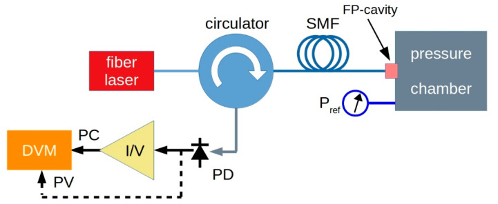
Figure 7.
Schematic of the experimental set-up. An IR fiber laser is coupled to the FP cavity by means of a circulator. The interference signal is detected by an InGaAs photodiode (PD). Either photovoltage (PV) or photocurrent (PC) signal are acquired as a function of the pressure by a computer-controlled digital voltmeter (DVM). For photocurrent acquisition, a current-to-voltage (I/V) photodiode amplifier is inserted.

