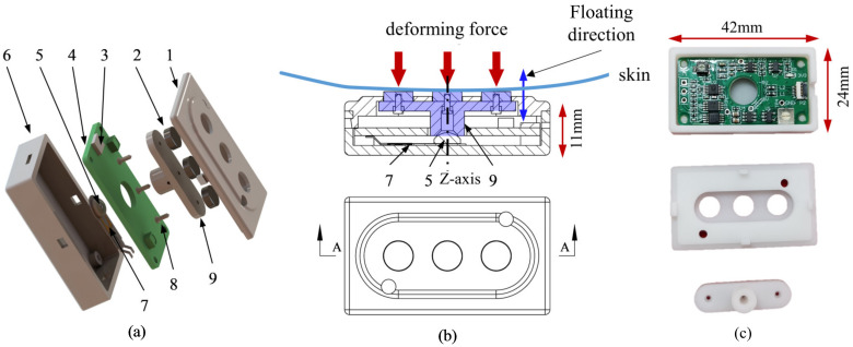
Figure 4.
The mechanical structure of the hybrid EMG–FMG sensor. (a) The exploded view of the structure. 1: The cover structure, 2: The three electrodes, 3: The FPC connector, 4: The PCB, 5: The silicon pad that sticks on the center of the FSR, 6: The containing box, 7: The FSR, 8: The screw for fixing, 9: The force beam that transmits the force applied on the electrodes. (b) The illustration of the force transmission to FSR. (c) Photos of the fabricated shell (3D printed) and the PCB.

