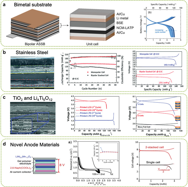
Figure 4.

Typical strategies for enabling BEs in LIBs: a) Schematic illustration of the bipolar ASSBs and galvanostatic charge–discharge profiles of three‐cell bipolar cells. Reproduced with permission.[ 56 ] Copyright 2018, Wiley‐VCH. b) SEM image of inner structure of bipolar LIB using SS and comparison of charge/discharge profiles after the fifth cycle. Reproduced with permission.[ 59 ] Copyright 2018, Royal Society of Chemistry. c) Schematic of inner structure of bipolar LIB, wherein both LiCoO2 cathode and Li4Ti5O12 anode use the Al foil as a current collector, as well as the preparation processing. Reproduced with permission.[ 28 ] Copyright 2018, Royal Society of Chemistry. d) Charge/discharge profiles for an Li/2,6‐Naph(COOLi)2 cell (inset: corresponding cycling performance) and charge/discharge profiles of two stacked bipolar 2,6‐Naph(COOLi)2/LiNi0.5Mn1.5O4 cells (inset: corresponding cell configuration). Reproduced with permission.[ 64 ] Copyright 2014, Wiley‐VCH.
