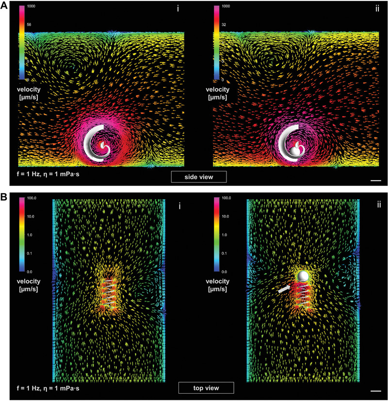
Figure 5.

Fluid dynamics simulations (ANSYS 17.2 Academic software) of loaded and unloaded micromotors in water‐based medium (η ≈1 mPa s) at 1 Hz rotation after five complete rotations, logarithmic color scales of flow velocities around micromotors (different for spiral and helix) indicate fluid velocity: A) spiral without (i) and with (ii) spherical cargo (side view); B) helix without (i) and with (ii) spherical cargo (top view), white arrow marks a significant flow disturbance; all scale bars are set at 100 µm; please refer to Figure S4A,B, Supporting Information for results in high viscosity (1 mPa s).
