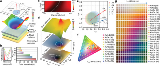
Figure 2.

a) Contour map of the calculated reflectance versus complex refractive index at a specific wavelength (λ c = 500 nm), along with a schematic of the composition of each separated HLRP layer. b) Color saturation of each reflectance spectrum having different dip reflectances (R dip) (λ dip = 500 nm). c) Reflectance contour with dynamic change of coating layer on the HLRP of Au/Ge (P r 75%, t Ge = 60 nm). d) RGB color representations and corresponding color differences (ΔE) with different coating layers on 2D surface of complex refractive index. e) Complex refractive index coordinate, which contains resonant area for various materials. As P r increases, the complex refractive index of HLRP converges to the resonant area. f) Chromaticity plots for sRGB gamut (white line) on CIE coordinates, indicating the colors of phage‐coated HLRP for various material and thickness combinations. g) Color palette of several material and thickness combinations with dynamic change (t coat 60–200 nm).
