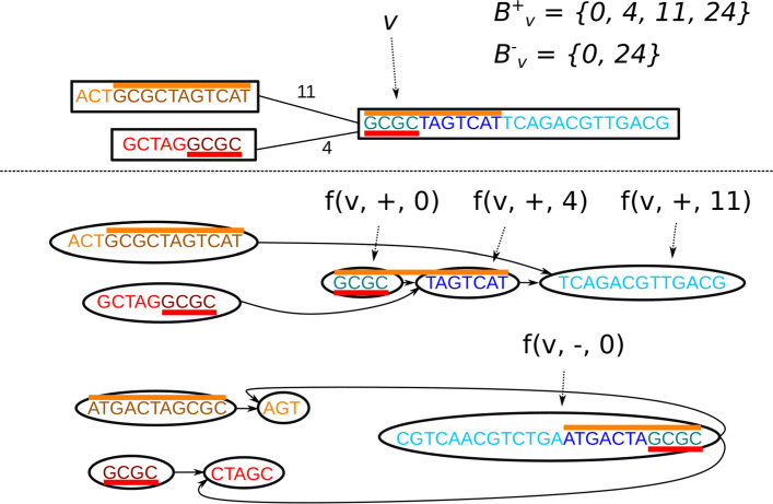
Fig. 4.
Converting a bidirected graph with variable edge overlaps to an alignment graph. Top: a bidirected graph with three nodes. The edges are labeled by their overlap. The red-colored bars represent the same sequence, which should not be duplicated during traversal. Similarly, the orange-colored bars represent the same sequence. Bottom: the alignment graph created from the top graph. The colors of the base pairs show how they match between the two graphs, with each sequence in the original graph represented by the same color in the alignment graph twice, once for the forward strand and once for the reverse complement. Similarly to the bidirected graph, the red and orange bars represent the same sequences. There are two subgraphs, one representing the forward traversal (top) and one the backward traversal (bottom) with reverse complemented node labels. Each edge introduces a breakpoint in the target node, splitting the node at the boundary of the overlap. The alignment graph then connects the ends of the overlap such that the overlapping sequence is only traversed once

