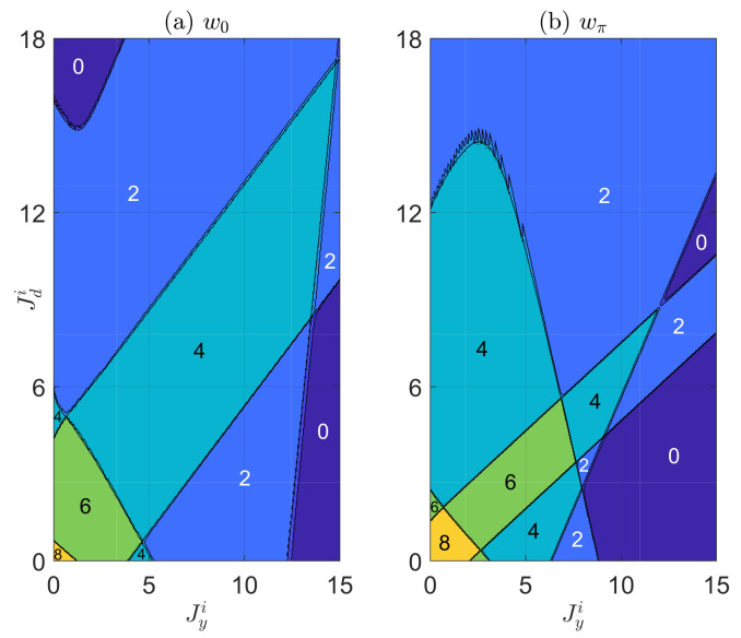
Figure 3.
The topological winding numbers [in panel (a)] and [in panel (b)] versus the imaginary parts of vertical and diagonal hopping amplitudes and . The other system parameters are set as . In both panels, each region with a uniform color refers to a Floquet topological phase of the non-Hermitian PQTLL model, with the values of winding numbers shown explicitly in the figure. The lines separating different regions are the boundaries between different non-Hermitian Floquet topological phases, which can be obtained numerically by setting and in Equations (9) and (10).

