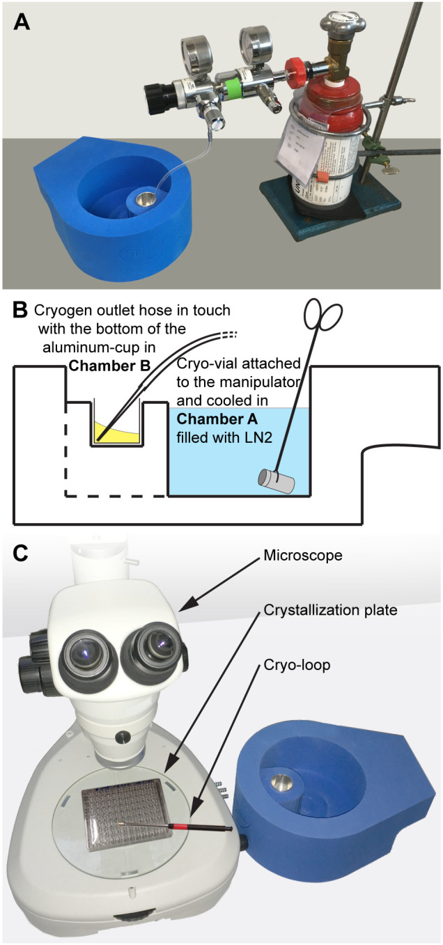
Fig 2. Illustration of the macromolecular flash-cooling procedure.

(A) Image displaying the cryogen condensation procedure with the double-chambered flash-cooling device placed next to the propane or ethane gas bottle. (B) Cartoon describing two different situations, i.e., i). during the cryogen condensation procedure, the gas outlet hose is in contact with the bottom of the aluminum cup in Chamber B (liquid cryogen highlighted in yellow) and ii). after cryogen condensation and prior to crystal harvesting, a cryo-vial is placed into LN2 (highlighted in blue). (C) For crystal harvesting, the device is with its Chamber B positioned as close as possible to the microscope to minimize the distance between crystal harvesting site and Chamber B.
