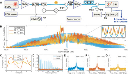
Fig. 2. Frequency division of a soliton microcomb generated by a crystalline microresonator.

(A) Experimental setup. A fiber Bragg grating (FBG) and a circulator are used to separate the pumping external cavity diode laser (ECDL) from the solitons. A photodetector (PD1) and an electro-optic modulator (EOM) are used to produce PDH signals to lock the laser-resonance detuning. Half of the GSL power is registered by a photodetector (PD2) to produce subharmonic locking error signals. A servo locks the gain switching frequency to be an integral submultiple of frep via frequency modulation (FM) of the signal generator. Simultaneously, the dc output of the servo is used as an error signal to stabilize frep through amplitude modulation (AM) of the pump laser power with an acousto-optic modulator (AOM). (B) The optical spectra of the microcomb and the soliton-injected GSL gain-switched at frep/2 and frep/3, respectively. The inset shows an enlargement of a portion of the spectra. (C) The error signals generated by PD2. The dashed line indicates the locking point. (D) The power spectra of the soliton-injected GSL when the SPL is on (red) and off (blue). (E to G) The spectra of DKS frep and the phase-locked gain switching frequencies at frep/2 and frep/3, respectively.
