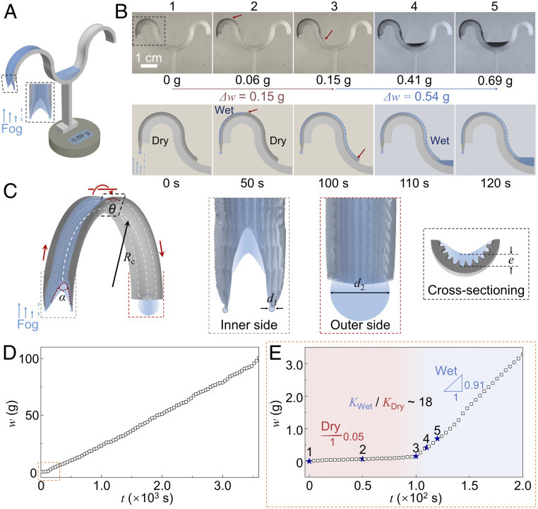
Fig. 3.
Artificial peristome water harvestor. (A) Schematic diagram of the artificial peristome harvestor. (B) Time-sequence images of the water condensation and transport process on the artificial peristome harvestor. (C) The mechanism for enhancing water transport speed. The water droplet with a diameter d1 condensate at the cone side transports along the wet surface to the container side. The energy release induced by the surface energy of the droplets converts to the kinetic energy for water to overflow the arch. (D) Water-harvest weight (w) versus time (t) for the water fog collected on the artificial peristome harvestor. (E) The water-harvest weight (w) versus time (t) during the initial water condensation state.

