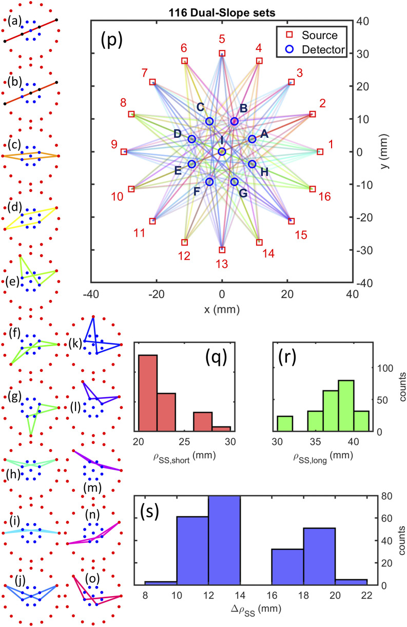
FIG. 6.
Circular design of the Dual-Slope (DS) imaging arrangement. [(a)–(o)] Examples of each of the types of DS sets within the source–detector arrangement. (p) Full array showing all sources (1–16), detectors (A–I), and SD measurement pairs (lines). (q) Histogram of all Single-Distances (SDs) that make up the short distance of a Single-Slope (SS) set. (r) Histogram of all SDs that make up the long distance of a SS set. (s) Histogram of all distance differences for SS sets.

