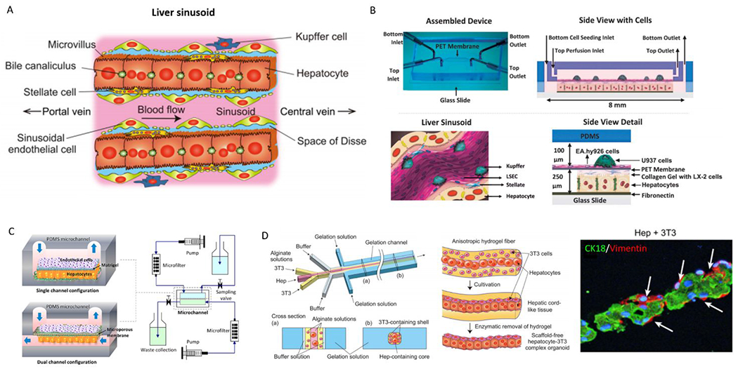
Figure 16.

Overview of microfluidic device designs to mimic the liver. (A) Structure of the hepatic cord in the liver lobule. Parenchymal hepatocytes are separated from the sinusoid and are arranged in cord-like structures with a thickness of 1-hepatocyte layer. (B) Image of assembled microfluidic device (top left), schematic of device cross-section (top right). Representative schematic of the liver sinusoid microanatomy recapitulated by the model (bottom left). Hepatocytes are co-cultured with stellate cells (LX-2) in the bottom channel, endothelial cells line the PET membrane, and Kuppfer (U937) are cultured in the top channel (bottom right). (C) Two microfluidic platforms: single channel and dual channel configurations (left); and bioreactor circuit for continuous perfusion of media and waste collection (right). (D) Microfluidic system for fabricating sandwich-type alginate hydrogel microfibers that incorporate hepatocytes and 3T3 cells (left). Representative images of hydrogel fabrication (middle) and microscopy images of model (right). 178, 179, 182. Reproduced with permission from John Wiley and Sons, from ref. 178 copyright 2013; from Ref 179, copyright 2015. Reproduced from ref 182 with permission Elsevier, copyright 2012.
