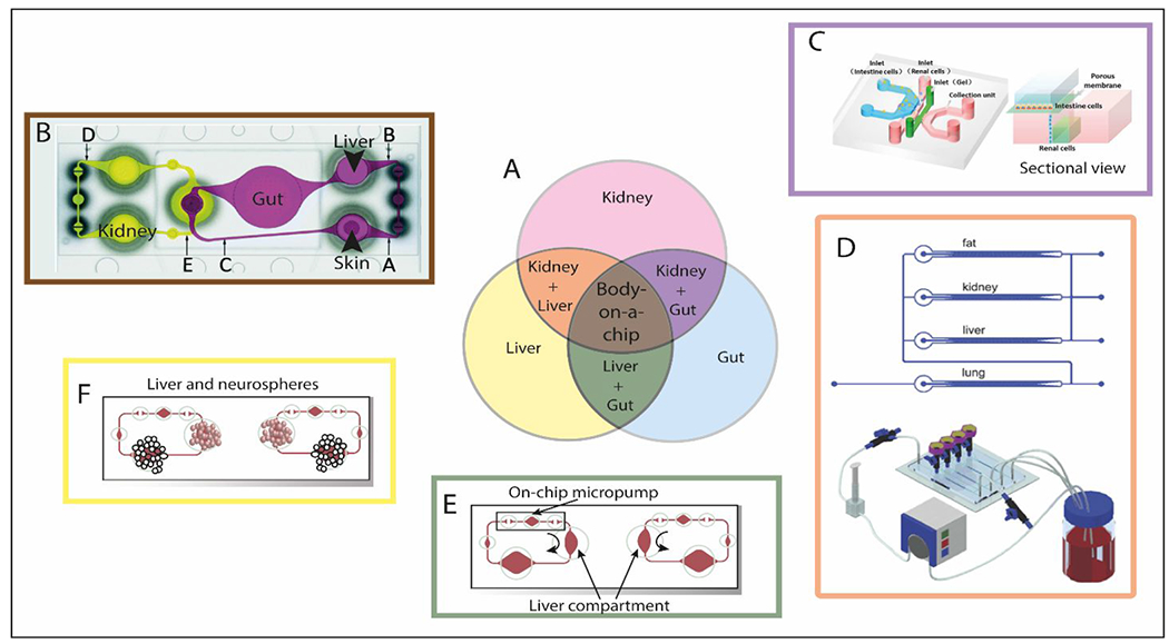
Figure 18.

Multi-organ models: toward the body-on-a-chip. (A) Schematic of the most modeled organs and multi-organ interactions on chips. The color code of this schematic is used in the rest of the panels. (B) Top view of the four-organ-chip layout illustrating the positions of three measuring spots (depicted as A, B and C) in the surrogate blood circuit and two spots (depicted as D, E) (C) Schematic diagram of the design of intestine-kidney chip and sectional view. The top layer, porous membrane, and bottom layer were sealed together. The intestine cells were cultured in the chamber on the top layer, and renal cells were seeded in the chamber on the bottom layer. (D) Schematic representation of the multi-organ model called “multi-channel 3D-pFCCS” (top). Close-loop perfusion culture of cells (bottom). During culture, the A549 (lung) channel was closed to facilitate medium perfusion in a serial manner. (E) Experimental setup of the multi-organ liver-gut model for reproducing first-pass metabolism. (F) Experimental set up of single cultivation and co-cultivation of neurospheres and liver microtissues.153, 194–197. Reproduced from ref. 153 with permission from AIP Publishing, copyright 2017.
