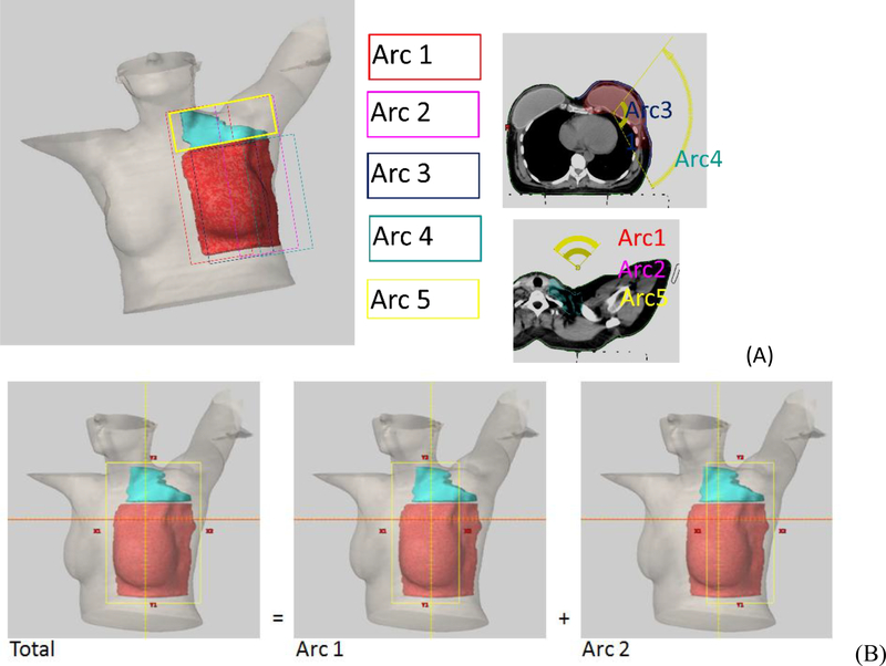
Figure 1.
Arc geometry of a left sided Arm Avoidance VMAT plan. All arcs have the same isocenter and no couch rotation is needed. Figure 1A illustrates the arc arrangement of a 5 arcs plan. Red is PTV-CW and Cyan is PTV-SCV. Arc1 and Arc2 cover both PTV-CW and PTV-SCV but no segment enters thought ipsilateral arm. Arc5 has the same arc setting as Arc1 or Arc 2 but with 90-degree collimator angle and covers primarily PTV-SCV. Arc3 and Arc4 cover PTV-CW and superior borders are below ipsilateral arm. Figure 1B illustrates how x jaw positions were set. This is an example for Arc1 and Arc2. Total x jaw needed for covering the PTV is X1total = xx, X2total =yy. Arc 1’s X1 is then set to xx, X2 = 14.8-xx, and Arc 2’s X2 is set to yy and X1 = 14.8 − yy. Every arc can fully modulate within Varian machine’s X-jaw width limit of 14.8cm for Truebeam (14.5 cm for other series).

