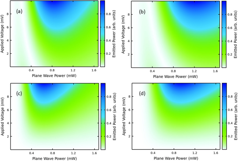
Figure 4.
Asymmetric versus Symmetric current flow. Calculated harmonic powers under asymmetric (a, b) versus symmetric (c, d) current flow for the fourth (a, c) and sixth (b, d) harmonics with an input field oscillating at =120 GHz. The input has been calibrated by simulated annealing as explained in the “Methods” section. In each panel the color bar is normalized to the maximum power output within the voltage range (0, 10) mV. The goal here is to show the clear that there is no emission around zero voltage for symmetric current flow in contrast with the asymmetric flow case.

