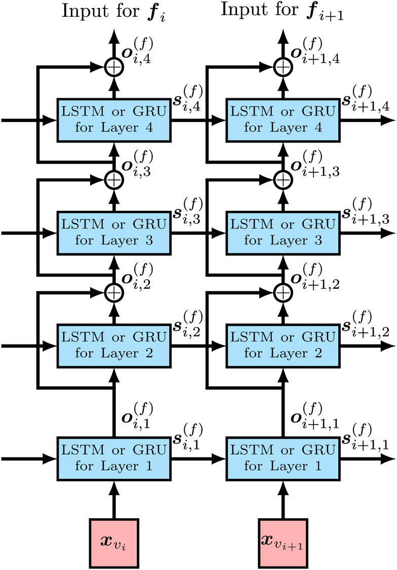
Fig 4. The structure of the forward RNN for each observed variant with residual connections for the case of four stacked RNN cells.
and are input feature vectors for observed variants vi and vi+1, respectively. is the state of the RNN cell of the jth layer for observed variant vi and used as the input of the state for the RNN cell of the jth layer for observed variant vi+1. Circles with + represent the addition of tensors for residual connections. The output of the RNN cell of the top layer, oi,4, is handled as the output of RNN for each observed variant.

