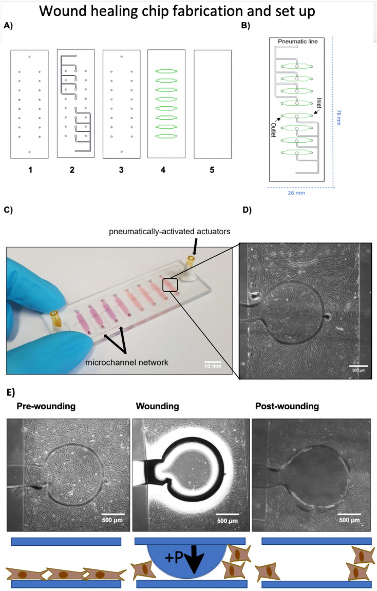
Figure 1.
Schematic illustration of the wound healing-on-a-chip microdevice. (A) Structure of five different layers used in fabrication of the wound healing microdevice. (1) Drilled glass slide, (2) PDMS pneumatic layer, (3) PDMS middle layer, (4) PDMS microchannel layer and (5) glass slide. During assembly layers 1, 2 and 3 as well as layers 4 and 5 were bonded initially prior to complete assembly to ensure optimal alignment of the layers and connections. (B) 2D structure of the microdevice including inlets, outlets and pneumatic lines. (C) Actual photograph of the microdevice consisting of eight microchannels filled with pink dye featuring two individually addressable pneumatically-activated actuator ports. (Scale bar = 10 mm). (D) Close up view of a single microchannel with defined circular wound actuators with a diameter of 1.4 mm located in the center of the microchannels. (Scale bar = 500 µm). (E) Illustration of the on-chip cell depletion procedure including a pre-wounding stage for monolayer growth, a wounding stage where pressure is applied on the flexible membrane and a final analytical post-wounding stage where the cell migration of fibroblasts into the wounded cell-free area created by membrane deflection is analyzed over time. (Scale bar = 500 µm).

