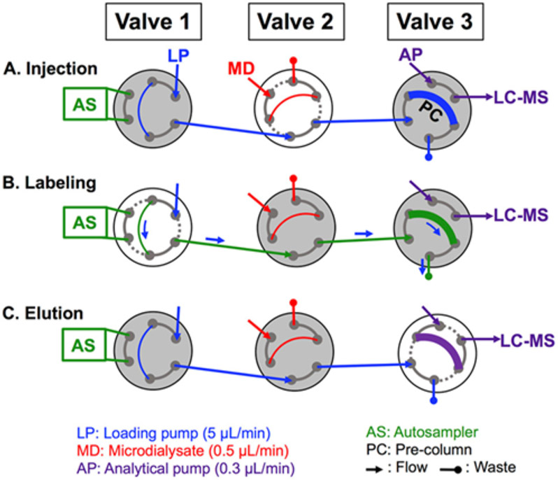
Figure 10.
Schematic for two-column labeling setup. Valve 1 is housed on the autosampler, Valve 2 is housed in the LC column oven, and Valve 3 is an external valve housed on the MS stage. Valve 2 is a 10-port valve but is depicted with 6-ports for clarity. White indicates a valve that is switching. Labeling is performed in the following way: (A) A 5 μL sample loop on Valve 2 is filled with microdialysate (MD), and upon switching, the sample is directed onto the precolumn (PC) by the loading pump (LP). (B) A series of five autosampler (AS) injections delivers reagents from vials (In sequential order: light labeling reagent, formic acid, 100 pM peptide aqueous standards, heavy labeling reagent, and formic acid) onto the PC, which react with peptides that have adsorbed onto the PC. (C) Valve 3 switches, directing flow from the analytical pump (AP) through the PC and eluting peptides off the PC and onto the analytical column-mass spectrometer (LC-MS) by gradient elution. Reprinted with permission from R. E. Wilson, A. Jaquins-Gerstl and S. G. Weber, Analytical Chemistry, 2018, 90, 4561-4568.

