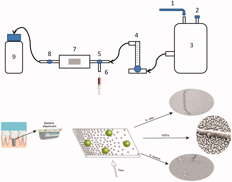
Figure 2.
Flow chamber setup. 1: Pressurized air supply. 2: Air output. 3: Water tank. 4: Flow meter. 5: Right valve. 6: Syringe input. 7: Flow chamber with gradient sample (graphical example of the surface below). 8: Left valve. 9: Waste container. Arrows show direction of the flow. Implant image, reprint permission from Shutterstock illustrations-Number: 548568394/TrifonenkoIvan.

