
Figure 1.
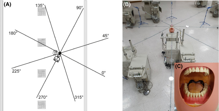
A, Schematic diagram of experimental set up. Position of air vents shown; square vents = air intake; long vents = air output. Experimental set up shown with collection positions labelled (note: degrees are relative to facing the mannequin). B, Photograph of experimental set up showing platforms spaced at 0.5 m intervals to support filter papers. C, Demonstration of polyvinyl siloxane addition to mouth of mannequin [Colour figure can be viewed at wileyonlinelibrary.com]