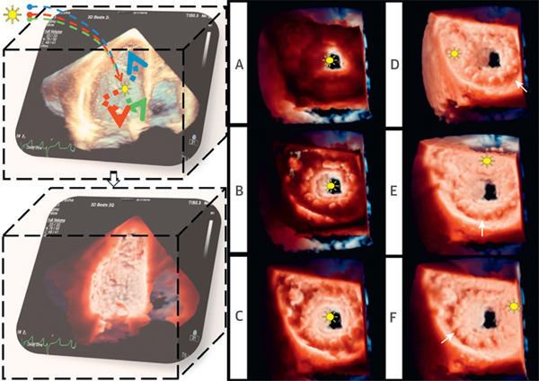
FIGURE 1. Principles of Transillumination Rendering.

(Left) TI post-processing. The light, modeled with multiple wavelengths, is positioned in the data set. Tissue absorption creates shadows, highlights structures, and enhances depth perception. (Right) Effect of changes in the light position. (A to C) The light was moved along the z plane (depth) from the left ventricular to the left atrial cavity. (D to F) The light was moved along the x and y planes within the LA. Different light positions determine different bioprosthesis shadows (white arrows) (Video 1). LA = left atrium; TI = transillumination.
