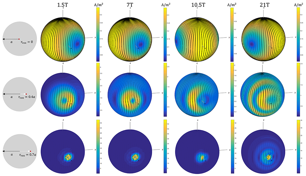
Figure 3: Snapshots of ideal current patterns yielding the optimal transmit efficiency at different voxel positions, for various main magnetic field strengths.

The density of ideal current patterns at ωt = 0 is shown for the spherical sample with radius a = 10 cm, for voxels at the center (rvox = 0), at an intermediate position (rvox = 0.4a), and near the surface (rvox = 0.7a). The voxel positions are shown in the first column. The other columns show the corresponding ideal current patterns for increasing B0 = 1.5, 7, 10.5, 21T. The shape and density of the ideal current patterns vary significantly among different voxel positions. Specifically, at the center, they resemble two large distributed loops on opposite sides of the sphere precessing at the Larmor frequency for all field strengths. At the intermediate and near-the-surface positions, they become increasingly localized around the target voxel. As the magnetic field increases, their shape becomes more complex, especially for intermediate voxel positions.
