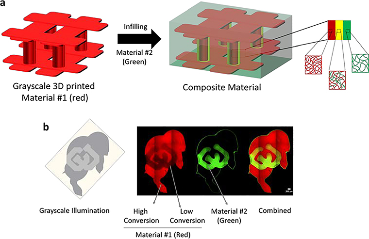
Figure 1.
Schematic of a 3d printed stiff material #1 containing pillars bound by an upper and lower lattice that is formed by stereolithography (SLA) (red) and then is infilled with a soft material #2 (green). During 3D printing, a thin shell around the columns is intentionally polymerized at low conversion to create regions that allow transport of the soft polymer into the 3D printed structure. This defines the region of integration (yellow). In the absence of these regions, transport of the soft material is prevented and an abrupt interface forms. When partially converted regions are patterned, transport of the soft material is achieved and an interpenetrating network forms between the soft and stiff materials (i.e., polymers) creating a strong interfacial bond. b) Demonstration of controlled selective transport in Ralphie (the buffalo mascot of the University of Colorado at Boulder). The gray scale image representing the energy dose distribution (left) was used to print a stiff polymer tagged with a red fluorophore containing regions of high and low conversion. Interpenetration of the soft polymer tagged with a green fluorophore was restricted to regions of low conversion and absent in regions of high conversion. The confocal fluorescence microscopy image demonstrates the controlled integration of the two within the block letters ‘CU’.

