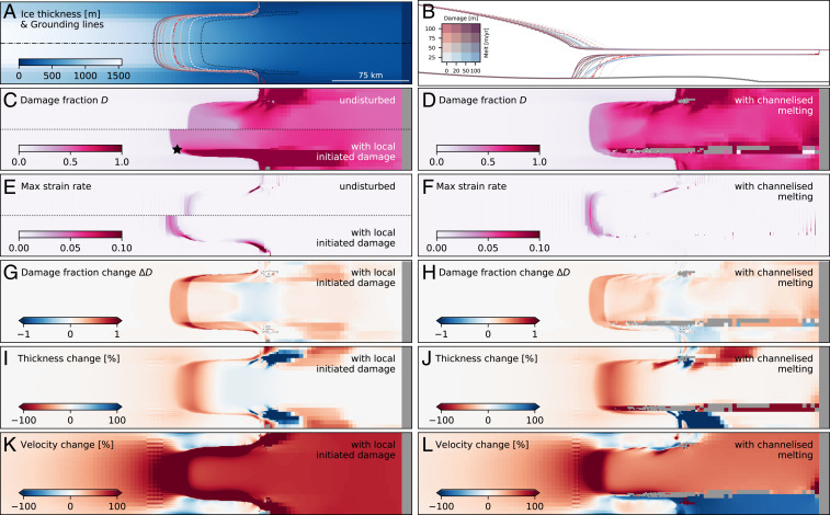
Fig. 3.
Ice sheet model with damage feedback result (see Movie S6 for animated version). (A) Initial ice thickness in BISICLES ice sheet model with initial grounding line (black dotted line). Grounding lines after 100 y model simulation for different model forcings are illustrated in colors corresponding to key in B. Dashed lines are used for no initial damage and solid lines for damage via introduction of crevasses at the location of star in C on both sides of the shear margin, while the red dotted-dashed line corresponds to channelized melting scenario. Black dashed-dotted lines illustrate location of profile in B. (B) Profile showing the geometries and grounding lines locations for different model forcing corresponding to different colors (see key) where dashed lines represent no initial damage, solid lines show runs for damage via introduction of crevasses at the location of the star in C, and the red dotted-dashed line corresponds to a channelized melting scenario. (C) Integrated damage for 25 m/y oceanic melt at grounding line with 20 m enhanced damage. Upper half shows simulation without the local damage enhancement at the grounding line, whereas Lower half shows simulation with damage enhancement at the grounding (at location of star) via introduction of crevasses. (D) Integrated damage for 25 m/y oceanic melt at grounding line with 20 m enhanced channelized melting in the lower shear zone. Gray values represent areas where the ice thickness is 0. (E) Maximum (Max) strain rate for simulation without/with (Upper/Lower half) enhanced damage at the grounding line. (F) Max strain rate for simulation with channelized melting. (G–L) Changes in damage fraction (G and H), thickness (I and J), and velocity (K and L) in 25 m/y melt run without/with 20 m vertically integrated crevasse depths implemented in the shear zone at grounding line (G, I, and K) and without/with channelized melting (H, J, and L), respectively, where negative/positive values represent thinning/thickening/increased values or slowdown/speedup/decreased values due to damage introduction and channelized melting, respectively.

