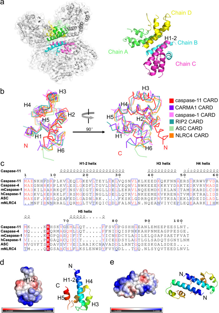
Fig. 2. Overall structure of caspase-11 CARD.
a Homotetrameric packing of caspase-11 CARD in crystal. The H1–2 helices reside in the center of the interaction interfaces. b A stereo diagram of superimposed known CARD structures: CARMA1-CARD (PDB ID: 4jup), caspase-1-CARD (PDB ID: 5fna), RIP2-CARD (PDB ID: 6ggs), ASC-CARD (PDB ID: 5gpq), NLRC4-CARD (PDB ID: 6n1i), and caspase-11 CARD. c Sequence alignment of residues 1–101 of caspase-11, caspase-4, mcaspsae-1, hcaspase-1, ASC, and mNLRC4. Different amino acids are in white and conserved residues are highlighted in red. The secondary structure of caspase-11 CARD is shown above the sequence. d An electrostatic surface of Chain C generated with APBS software. Negatively charged regions are represented in red, neutral regions in white, and positively charged regions in blue. Locations of the hydrophobic interface are indicated. The N terminus sequence of H1–2 contains neutral amino acids (white). The direction of the chain (N–C terminus) is colored as blue to red. e An electrostatic surface representation of Chain A and D generated with APBS software. Negatively charged regions are represented in red, neutral regions in white, and positively charged regions in blue. Locations of the hydrophobic interface are indicated. For each chain, the N terminus sequence of H1–2 contains neutral amino acids (white). The direction of the chain (N–C terminus) is colored as blue to red.

