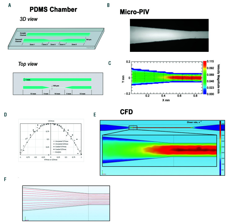
Figure 1.
Schematic of a microfluidic flow chamber designed to generate shear gradients. (A) Schematic of the poly-dimethylsiloxane (PDMS)-based microfluidic flow chamber containing a straight rectangular channel with a width of 1 mm and a height of 0.1 mm, and a stenosed channel with similar dimensions, but presenting a 90% reduction in width in the central region. (B) Bright field microscope view of the microfluidic flow chamber: transition from zone 2 to zone 3 of the stenosed channel. (C) Velocity magnitude heat map at mid-height in the stenosed channel obtained by micro-particle image velocimetry: transition from zone 2 to zone 3. (D) Non dimensional velocity profiles U⁄Umax as a function of Y⁄Ymax or Z⁄Zmax (U is the velocity magnitude, Ymax is the half width of the stenosis, Zmax the half height) in the mid height and mid width of the microfluidic flow chamber in zone 3. (E) Computational fluid dynamic analysis presenting the wall shear rate (WSR) heat map at the chamber floor (z=0) throughout the whole chamber and in the zoomed region corresponding to the entrance of zone 3. Channel geometry in the computational fluid dynamic simulation (CFD) model corresponded to the stenosed version of the chamber shown in panel (A). (F) The streamlines for the central horizontal crosssection (50 μm above the chamber floor) of the zone 2 to zone 3 connection region were calculated using the CFD-derived velocity field.

